8 Lens principles
The book is still taking shape, and your feedback is an important part of the process. Suggestions of all kinds are welcome—whether it’s fixing small errors, raising bigger questions, or offering new perspectives. I’ll do my best to respond, but please keep in mind that the text will continue to change significantly over the next two years.
You can share comments through GitHub Issues.
Feel free to open a new issue or join an existing discussion. To make feedback easier to address, please point to the section you have in mind—by section number or a short snippet of text. Adding a label characterizing your issue would also be helpful.
Last updated: November 6, 2025
8.1 Lens principles overview
A small pinhole renders a perfectly good image. Why do we need to add any optics? The critical reason is that pinhole apertures, by definition, only measure a small amount of electromagnetic radiation. We often find ourselves in conditions where the amount of radiation passing through the aperture is a limiting factor. We need more signal!
Let me tell you what I mean by small. Suppose we are in a dim room illuminated with a broad wavelength spectrum (10 \(cd/m^2\)). Consider a camera with a 1 mm pinhole, a sensor with 1 micron pixels, a focal length of 4mm, and an exposure duration of 50 milliseconds. In that case only about 35 photons arrive at each pixel. If we want to see in color, we must further divide up the wavelength range and the situation worsens. Because of the inescapable photon noise, which I describe later, this signal only permits a reliable intensity discrimination when two pixels differ by more than 20% (i.e., one edge is 20% brighter than the other, see fise_opticsCountingPhotons).
A lens, or more generally optics, is a way to enlarge the entrance aperture to acquire more photons, without paying a big penalty in spatial blur or geometric distortions. This ability must have great value because the solution has been used by many different animal species.
The most primitive animal eyes are called ‘pigment cup’. These are made of a small receptor surface, about 0.1mm in diameter, and the eye is simply open. The size of the opening is a bit large to be considered a pinhole. The eyes of some animals, in particular molluscs, have pinhole architectures. The receptor surface itself is 10 mm in diameter, and the opening is 0.4 - 2.8mm. These eyes evolved about 500 million years ago and have little changed.

The vast majority of animals have evolved visual systems with a lens. You might enjoy this lovely article by Michael Land, a distinguished vision scientist who taught us much about animal vision systems.
8.2 Rays and wavefronts
In the section on thin lenses, we describe lenses and treat light as rays (geometric optics). The reader may find this odd, given the clear demonstration of light as waves Section 7.3, and the obvious failure of the ray model. But to model refraction, and many other optics characteristics, geometric optics is both intuitive and accurate. We will return to calculations using waves later, when we consider more advanced calculations (Chapter 13).
It is useful to draw the connection between geometric and wave representations. In wave optics a collection of rays headed in the same direction, and of the same wavelength and phase, are represented as a plane wave (Figure 8.2). We can visualize the wave by drawing a line through the peaks of their (in-phase, common amplitude) waves. We call this line the wavefront. The wavefront diagrams do not show the amplitude of the wave. Various ray-wavefront combinations are illustrated in the different panels of Figure 8.2.
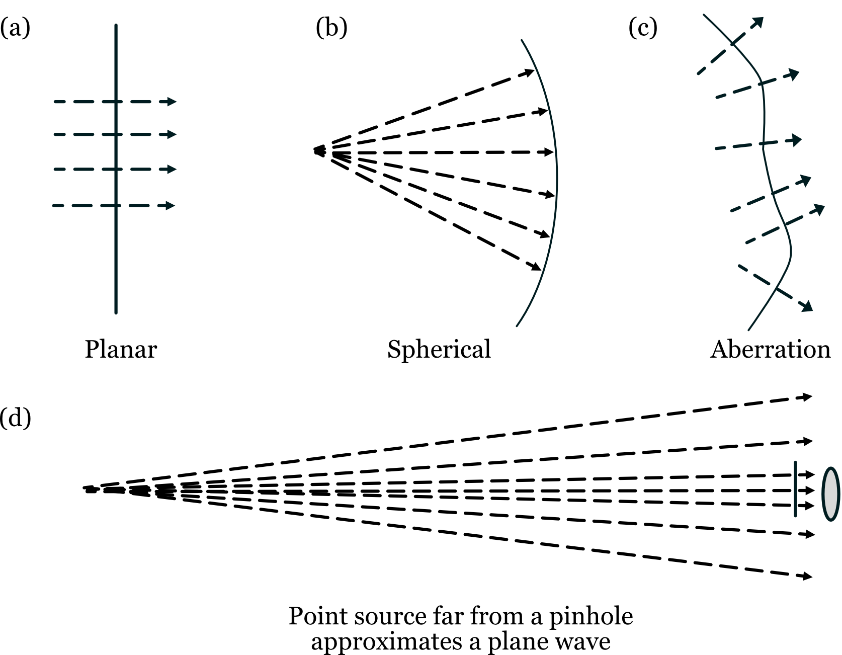
It is common for optics tutorials to represent wavefront directions as extended in space, but it is uncommon to represent the amplitude of the wavefront across space. In reality the amplitude of the wavefront will vary across space. For example, a typical laser emits a set of parallel (collimated) rays. The amplitude of these rays has a Gaussian profile that limits the wavefront in space. That’s why the spot a laser pointer produces is limited in space. In recent years, image systems engineers have had access to spatial light modulators (SLMs) (Section 8.6.5). These devices modulate either the local amplitude or phase of the wavefront at different positions in space, controlling the light field.
The software calculations that accompany this book use both wavefront and ray methods1.
8.3 Material interactions
When a light rays arrive at the boundary between regions with different optical properties - whether those regions contain matter (like glass or water), air or vacuum - several things can happen (Figure 8.3). The rays might be reflected back, as in a mirror. Or, the rays might enter into the material, undergo a series of internal reflections, and emerge back in one of many different directions. Also, the rays might enter the material and be absorbed, giving up their energy to the atoms in the material. (Maybe reference the dichromatic reflection model here?)
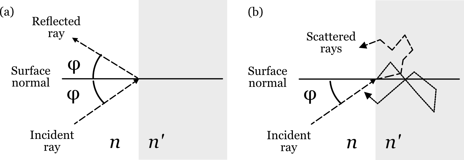
The most important case for controlling the rays, and thus for optical design, is this other possibility: the ray enters the new material and continues on its way. We call this change in direction refraction.
8.3.1 Snell’s Law
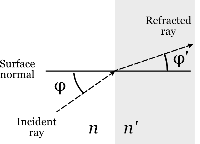
Snell’s Law quantifies how light changes direction when passing between regions with different optical properties. The mathematical formulation of Snell’s Law is defined using the variables shown in Figure 8.4. A light ray (Incident ray) is shown crossing a planar boundary between one medium (say, air) in a second medium (say, glass). The angle between the incident ray and a line perpendicular to the surface (the surface normal) is \(\phi\). The refracted ray changes direction and thus has a different angle, \(\phi '\), with respect to the surface normal. Snell’s Law captures the relationship between these two ray angles
\[ n \sin(\phi) = n' \sin(\phi') \tag{8.1}\]
The variables \(n\) and \(n'\) are the refraction index of the materials, which is related to the speed of the electromagnetic radiation in the material.
\[ n = \frac{c}{v} \tag{8.2}\]
where \(c\) is the speed of light in a vacuum, \(v\) is the speed in the material. By definition, \(n=1\) in a vacuum. It is very close to \(1.0\) in air. In some materials, such as glass, the velocity of light is much slower, so that the index might be \(1.3\) or even \(1.5\).
In many common materials the velocity is reduced because the light, which is electromagnetic radiation, induces an electrical signal in the electrons of the material. The specific properties of this signal depend on the material. The induced electrical signal sums with the electrical field of the light. The combined signal is predicted to travel slower and in a different direction, with the exact change in speed and direction dependent on the electrical properties of the material2.
Interestingly, there are less common materials (e.g.,liquid crystals) that have more complex interactions with the electrical field of light. These materials create interesting and useful effects (birefringence) that we will describe in Section 25.1.
This is a very nice tutorial from Fermilab about the physical basis of refraction. The speaker first discusses various common -but wrong- explanations. He then explains refraction using principles derived from Maxwell’s equations. Very clear and cool stuff.
8.3.2 Wavelength dependence
For many materials that index of refraction is wavelength dependent. Following Snell’s Law, light at different wavelengths change direction by different amounts. Consequently, when we set the lens to be in best focus for one wavelength, it will not be in best focus for other wavelengths. The inability to produce a good focus for all wavelengths simultaenously is called chromatic aberration.
For most materials the change of the refraction index over the visible wavelength is roughly linear, just varying in extent. It is common to summarize the dispersion using the Abbe number, \(V_d\), which is computed by comparing the refraction index at three different wavelengths.
\[ V_d = \frac{n_{489.3} - 1}{n_{486.1} - n_{653.3}} \tag{8.3}\]
Conventionally, an Abbe number greater than 50 implies very little dispersion and a number less than 30 implies significant dispersion that will impact image quality. The human eye has very significant chromatic aberration, with an Abbe number of about 15.
When possible, it is my preference in computation to provide numerical values describing the index of refraction as a function of wavelength and to measure the impact by computing the line spread or point spread function. We will perform analyses of chromatic aberration several times in this book, including in Chapter 22.
The Greek astronomer Ptolemy studed refraction in about the year 150 (Smith (1982)). He documented that rays passing from air into, say water or glass, change direction3. Ibn Sahl in Persia, around 930, quantified the change in direction as light crossed the boundary between certain materials, and he used this knowledge to design lenses.
The formula for refraction was discovered independently by two scientists in the 17th century. Willebrord Snellius (also known as Snell) first found the mathematical relationship in 1621, but his work wasn’t published during his lifetime. He was an astronomer, and in 1617 he determined the size of the earth based on measurements of its curvature between the cities of Alkmaar and Bergen-op-Zoom.
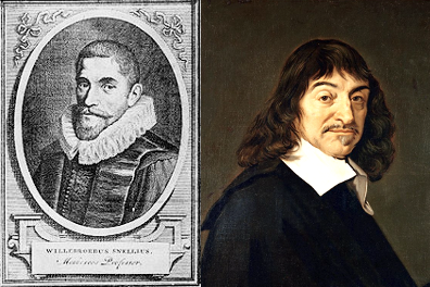
Renée Descartes independently discovered the relationship as well, and he published it in 1637. Although Descartes published first, the formula became known as Snell’s Law to acknowledge Snell’s earlier discovery. In modern times, the French still frequently refer to Snell’s Law as “la loi de Descartes” or “la loi de Snell-Descartes”.
The physicist Christiaan Huygens showed that Snell’s Law could be explained by treating light as a wave that travels at different speeds in different materials. More about the history of the discovery and quantification, including the references, makes for interesting reading.
8.4 Lenses control ray directions
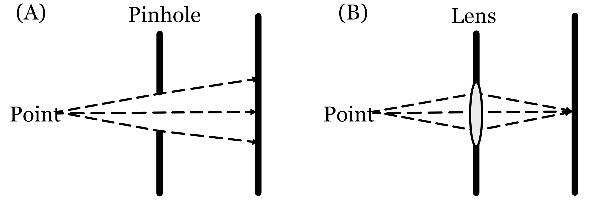
Consider the rays from a point as they pass through a pinhole. The image they form will not be sharp because the ray directions are diverging. Narrowing the pinhole sharpend the image formation by selecting a small subset of the rays.
We can sharpen the image by redirecting some of the rays to converge at the image plane. One way to think about optical devices is that they are built to control the direction of the environmental light field rays at the image system entrance aperture. When forming a sharp image is the goal, we evaluate the optics by asking whether they adjust the ray directions so that the image of a point in the scene is also a point. A useful fact to remember is that diffraction means the best (sharpest) we can do for a circular aperture is defined by the diameter of the Airy disk.
8.5 Making a lens
To make a lens that focuses a light field into an image plane requires changing the direction of many rays. The simple case of rays from one point is easy to see.
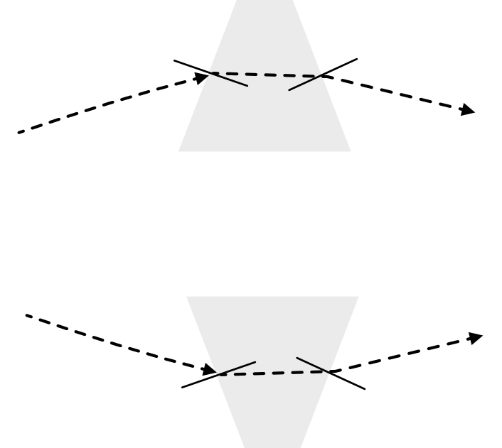
Imagine that the rays are diverging from an object point at the left. Were the rays passing through a pinhole, they would continue to diverge. Refraction by the prism changes the direction of the rays at the from upward to downward (upper prism). Similarly, refraction changes the ray directions from downward to upward (lower prism). These two prisms converge the rays from the object point onto a point on a properly positioned image plane.
Expanding on this idea, we can stack a collection of prisms to gather more of the rays. Or, more likely, we might polish a glass surface to have two spherical surfaces, forming a continuous form of the stacked prisms. The entrance aperture of this lens can capture much more light than a pinhole, and it guides the rays to converge. Spherical lenses are quite popular because they are easy to manufacture. Using Snell’s Law it is relatively straightforward to calculate the refraction for a ray arriving at any location on the sphere 4.
The diagram makes it clear that there are many lens design choices. For example, we might change the shape of the lens surfaces. Also, we might use different materials in the prisms. What considerations would guide such choices?
8.6 Innovations in Lens Design
An overarching goal in optical design is to create a lens that is free from imperfections, known as aberrations. The choices in lens design involve trade-offs between performance, cost, size, and weight. The following sections introduce a range of solutions, from classical to cutting-edge, that address these challenges.
8.6.1 Spherical Aberration
Spherical surfaces are relatively easy to manufacture and thus cost-effective. However, they have a fundamental flaw first documented by the 11th-century scientist Alhazen in his “Book of Optics” (Kitāb al-Manāẓir). He observed that spherical lenses produce blurry images because they refract light more strongly near their edges than near their center. As a result, rays passing through the periphery of the lens do not converge at the same focal point as rays passing through the center. This imperfection is called spherical aberration. The severity of this aberration depends on factors like the lens aperture, curvature, and material.
8.6.2 Multi-element lens
A classical solution to spherical and other aberrations is to combine multiple spherical lenses into a single optical system. In these multi-element optics, additional lenses are carefully arranged to cancel out the aberrations of the primary lens. Famous designs like the Double-Gauss or Petzval lens systems use this principle to achieve high image quality. While effective, this approach often results in large, heavy, and complex assemblies, as seen in high-end camera lenses. I will describe these classic designs in Section 10.4.2. As you will see, in the early days determining how to combine even a few spherical components was an intellectual challenge, and quite important.
Modern optics with multiple elements has achieved very remarkable advances. And, in some important cases, the size and weight are not a limit. The important company, ASML, working with Zeiss, has produced entirely remarkable lenses. These enable people to use lithography to manufacture of integrated circuits at nanometer resolution. Now that’s a lens.

8.6.3 Aspheric Lenses
Instead of adding more lenses, another approach is to change the shape of the lens surface itself. An aspheric lens deviates from a perfect spherical shape, with its curvature changing from the center to the edge. This tailored profile allows it to correct for spherical aberration in a single element, enabling more compact and lightweight designs.
Historically, aspheric lenses were difficult and expensive to produce. However, advances in computer-controlled polishing and glass/plastic molding have made them common in everything from smartphone cameras to research-grade instruments. The surface of an aspheric lens, its sag \(z\), is often described as a function of the radial distance \(\rho\) from the optical axis:
\[ z(\rho) = \frac{\rho^2 / R}{1 + \sqrt{1 - (1 + k)(\rho/R)^2}} + A_4 \rho^4 + A_6 \rho^6 + \cdots \tag{8.4}\]
Here, \(R\) is the radius of curvature at the lens vertex, \(k\) is the conic constant that defines the basic shape (e.g., parabolic, hyperbolic), and the \(A_i\) terms are higher-order coefficients that fine-tune the surface to minimize aberrations.
8.6.4 GRIN Lenses
Another way to control light is to vary the material properties within the lens instead of changing its surface shape. A gradient-index (GRIN) lens has a refractive index that changes continuously within the material, typically decreasing from the center to the edge.
Long before this became practical, in 1854, James Clerk Maxwell theorized that such a gradient could eliminate spherical aberration in a spherical lens, a design now known as the “Maxwell fisheye.” It was later discovered that many animal eyes use this exact principle. While more challenging to manufacture than aspheres, GRIN lenses offer unique design possibilities, especially in compact systems like endoscopes. Maxwell’s work in this area -and later when we discuss his work in color- are an example of the interplay between physics, engineering, and biology5.
8.6.5 Spatial Light Modulators
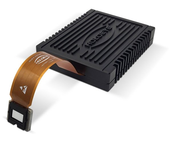
What if a lens could be reconfigured on the fly? Spatial light modulators (SLMs) are devices that can dynamically control the properties of a light field on a pixel-by-pixel basis. They are essentially programmable optical elements.
- Phase SLMs, often based on liquid crystal arrays, can locally alter the phase of light, effectively acting as a reconfigurable lens or diffraction grating. They can be used to correct for aberrations in real-time or to sculpt a light beam into a complex pattern.
- Amplitude SLMs, which use technologies like MEMS (micro-electro-mechanical systems) mirrors, modulate the intensity of light at each pixel.
With pixel sizes on the order of microns and arrays containing millions of elements, SLMs are powerful tools in adaptive optics, holography, and advanced imaging systems. This figure shows a recent phase SLM with extremely high resolution.
8.6.6 Metalenses
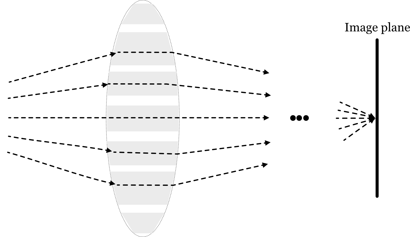
The most recent revolution in optics miniaturization comes from metalenses. These are not lenses in the traditional sense but are flat surfaces, like a sliver of glass, patterned with an array of nanoscale structures (“meta-atoms”). Each nanostructure is smaller than the wavelength of light and is engineered to impart a specific phase shift to the light passing through it.
By arranging these meta-atoms in a precise pattern, a metalens can bend light just like a conventional curved lens but without the bulk. This technology promises to replace complex, multi-element systems with a single, ultra-thin optical element. Researchers are developing metalenses that can perform sophisticated tasks, such as focusing different colors to the same point or routing specific wavelengths to different locations (Catrysse et al. (2022), Catrysse and Fan (2023)). While still an active area of research, metalenses have the potential to fundamentally change optical design.
Note: Fröch et al. (2025) dealing with chromatic aberration, broadband imaging challenge.
8.7 Onward
The next sections will take you through the logical development from the simple thin lens to the analysis of a thick lens, and then to multielement lenses. Those principles are the foundation that has led to these developments.
The ISETCam optics calculations uses the wave model. The ISET3d graphics calculations use the ray model.↩︎
This excellent pair of (nicely snarky) Fermilab videos from Don Lincoln explain the change in velocity and direction.. We can thank James Clerk Maxwell for providing the basis of this understanding.↩︎
In Chapter 26 of his book of lectures, “Optics: The Principle of Least Time”, Feynman works from Ptolemy’s data to derive Snell’s law (Feynman et al. (1963)). Some say that Ptolemy held back science by not noticing the relationship. Seems a bit harsh to me.↩︎
Put the formula for refraction of a ray at a spherical lens in here.↩︎
Michael Land’s Britannica article has lots of interesting examples of animal eyes and the story about GRIN lenses and Maxwell.↩︎