2 Light and seeing
The book is still taking shape, and your feedback is an important part of the process. Suggestions of all kinds are welcome—whether it’s fixing small errors, raising bigger questions, or offering new perspectives. I’ll do my best to respond, but please keep in mind that the text will continue to change significantly over the next two years.
You can share comments through GitHub Issues.
Feel free to open a new issue or join an existing discussion. To make feedback easier to address, please point to the section you have in mind—by section number or a short snippet of text. Adding a label characterizing your issue would also be helpful.
Last updated: November 6, 2025
2.1 Light and seeing overview
Electromagnetic radiation fills the world around us, providing a rich and reliable stream of information. Mobile organisms — whether a hawk, a rabbit, or a human — have implemented ways to sense and interpret this information. They use the information to make decisions and interact with their surroundings. We call the sensing and interpretation of the radiation visual perception or more simply, seeing.
Visual perception is fundamental for guiding movement, enabling animals to locate resources, avoid threats, and navigate their environments. The use of radiation for mobility and decision-making by mobile organisms is in contrast to immobile life forms, such as trees and plants. For these organisms the ambient radiation serves primarily as a source of energy, rather than information.
In robotics and most computer applications, visual sensing serves a similar purpose: to enable actions and movement within dynamic and complex environments. Robots with imaging systems identify and manipulate parts. Cars with image systems navigate through their surroundings. Medical imaging provides diagnostic information to guide interventions. Image systems provide information that enables goal-oriented actions for both artificial and biological systems.
The deep connection between mobility, visual sensing, and the brain is illustrated by the remarkable life path of the sea squirt. It begins life as tadpole-like larvae, equipped with a brain and a tail for swimming. Once the tadpole finds a suitable spot to settle, it attaches to a hard surface like a rock or coral and becomes immobile.
As soon as the sea squirt fixes itself to the rock, with no more navigation or swimming, its brain is no longer needed. In a truly bizarre twist, the sea squirt digests its own brain. This adaptation reallocates energy resources from the now unnecessary brain to more vital functions.

My Stanford colleague, Irv Weissmann, and his group wrote many papers about neurodegeneration using the sea squirt.
Consumer photography - a large and important image system application - is an exception. Consumer photographs are created to store memories and evoke emotions, not to guide navigation or immediate decisions. Because of photography’s deep connection to human perception, the technologies for evaluating consumer photography differ from the engineering metrics that are appropriate for robots, cars, and medical imaging. For this reason, we will devote considerable attention to the properties of the human visual system (Section 1).
In summary, some image systems measure electromagnetic radiation because the signal is useful for movement or interacting with objects. Other image systems measure radiation to record a moment, enabling us to reproduce the signals at a later time. And finally, some image systems measure electromagnetic radiation at wavelengths we do not see, enabling us to explore domains that are beyond our senses 1. The first section of the book is devoted to understanding the signal.
2.2 The electromagnetic spectrum
One of the great achievements of science is the realization that seemingly different phenomena are deeply connected. By the early 1800s, scientists had uncovered links between electricity and magnetism: Øersted (1820) showed that electric currents generate magnetic fields, and Faraday (1832) demonstrated that changing magnetic fields induce electric currents.
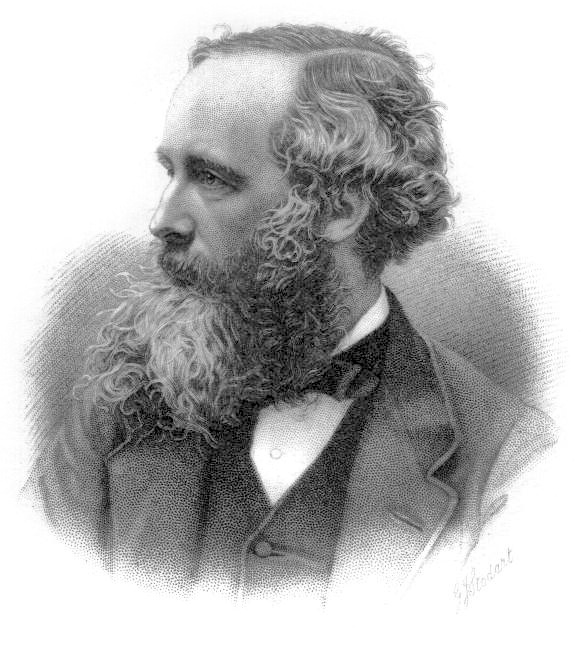
James Clerk Maxwell unified these discoveries in a set of mathematical equations, simplified by Heaviside, and now known as Maxwell-Heaviside equations. He demonstrated that oscillating electric and magnetic fields behave as waves that propagate through space. Remarkably, the predicted speed of these waves matched the measured speed of light. Maxwell concluded that light itself is an electromagnetic wave, thereby uniting electricity, magnetism, and optics into a single theoretical framework: electromagnetic radiation spanning a range of wavelengths.
We will encounter Maxwell’s work multiple times in this book. In addition to this remarkable unifying set of equations, we will see his insights about optics and his fundamental demonstrations of the properties of human color vision.
Einstein kept images of three scientists in his office —Isaac Newton, James Clerk Maxwell, and Michael Faraday. These captured the lineage of thought that led to his own work. Newton’s laws of motion laid the foundation for classical mechanics. Maxwell unified electricity, magnetism, and light with his equations, building upon the experimental work of Faraday, who originated the concept of electric and magnetic “fields.” Einstein’s theories of relativity were a direct response to Maxwell’s equations, and he saw himself as a successor to this great tradition. I have (several) friends who remind me that two of these three scientists were Scottish. I very much appreciate this homage to Newton by Neil de Grasse Tyson/
James Clerk Maxwell died in 1879 at the age of 48 from abdominal cancer. His mother, Frances Clerk Maxwell, also died from the same disease at the age of 48 when he was just eight years old.
2.3 Light
Not all electromagnetic wavelengths are equally useful for seeing. The human eye detects electromagnetic radiation within a specific range, approximately 380 nm to 770 nm. This range is referred to as light—electromagnetic radiation that is visible to the human eye. Radiation in this range is particularly useful for seeing because it is strongly absorbed and reflected by objects in the environment, making it ideal for detecting and interpreting the world around us.
In contrast, high-energy radiation, such as X-rays (0.01–10 nm) and gamma rays (< 0.01 nm), tends to pass through most objects without significant interaction. On the other end of the spectrum, low-frequency radiation (> 1500 nm) provides lower spatial resolution and is heavily influenced by thermal effects, limiting its utility for detailed imaging. The visible spectrum occupies a unique and advantageous position for vision and perception.
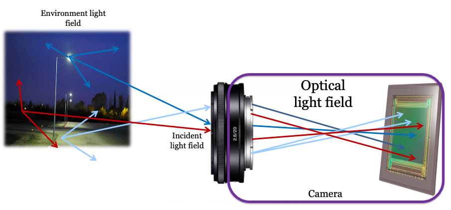
2.4 The environmental light field
Electromagnetic radiation fills the environment, traveling in all directions and interacting with the objects that surround us. We call the environmental radiation within the visible wavelength band the environmental light field.
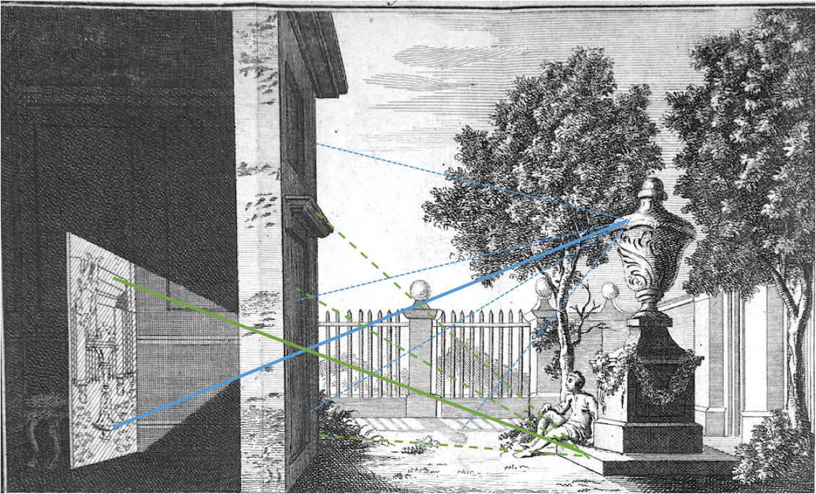
Leonardo Da Vinci’s notebook (Da Vinci 1970) describes why he concluded that light fills the environment. He placed a small hole in a wall of a windowless room that was adjacent to a brightly illuminated piazza (Figure 2.3). This produced an (inverted) image of the piazza on the wall within the room. Leonardo observed that one can place the pinhole anywhere in the wall and an image of the same objects is produced. He concluded that the light field is “all everywhere and all in each part”2.
For the moment, it is convenient to consider the light field as comprising a large set of rays. We can describe the light field in the environment, \(L_E\), by the intensity of each ray, expressing the intensity as a function of its various parameters. Rays cross through each point in the volume of space, \((x,y,z)\), in many directions. We specify these directions by two direction angles \((\alpha, \beta)\), the azimuth and elevation. Each ray has a wavelength \(\lambda\) and a polarization \(\rho\). The ray intensities are described by a function of seven parameters:
\[ L_E(x,y,z,\alpha,\beta,\lambda,\rho) \tag{2.1}\]
People in many fields are familiar with the concept of the light field, but they use different terminology. Physicists often describe the environmental light field as the spectral radiance of the environment (see this lovely description from Feynman). The light field terminology was introduced into optical engineering by Gershun (1939) as part of his work in understanding how to design lighting environments, such as the lighting in school rooms and public places3. Ted Adelson and Jim Bergen (1991) used the term plenoptic function to describe the same idea4. In computer graphics, the value of the light field concept was explained by Marc Levoy and Pat Hanrahan (1996). I use the light field terminology because I find it less intimidating than spectral radiance, electromagnetic radiation, or plenoptic.
2.5 The incident light field
An imaging system—whether an eye, a camera, or a simple pinhole—can only capture the portion of the environmental light field that reaches its aperture, or entrance pupil (Figure 2.4). We call this subset of rays the incident light field.
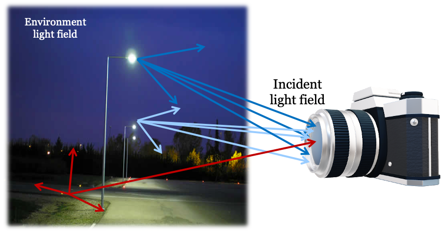
Because the incident light field is defined on the two-dimensional surface of the entrance pupil, we can describe it with fewer parameters than the full environmental light field. Instead of a 3D position in space \((x,y,z)\), we use a 2D position \((u,v)\) on the pupil plane. The complete description of the imaging system also requires its position in space, \(\mathbf{p}\), and its viewing direction, \(\mathbf{n}\). We treat these as fixed conditions for a given measurement.
The incident light field, \(L_I\), can then be expressed as a function of six variables, plus the system’s position and orientation:
\[ L_I(u,v,\alpha,\beta,\lambda,\rho; ~\mathbf{p},\mathbf{n}) \tag{2.2}\]
To capture the full environmental light field, we must follow Leonardo’s insight and measure the incident light field from multiple positions and directions. Many animals have two eyes, providing two simultaneous measurements. This redundancy not only offers a backup if one eye is damaged but also provides more information about the scene. Prey animals, like rabbits, often have eyes pointing in different directions to achieve a wide field of view. Predators, on the other hand, typically have forward-facing eyes with overlapping fields, which enables stereoscopic vision for depth perception. We also gather more information about the light field over time as we move our heads and our eyes rotate (motion parallax).
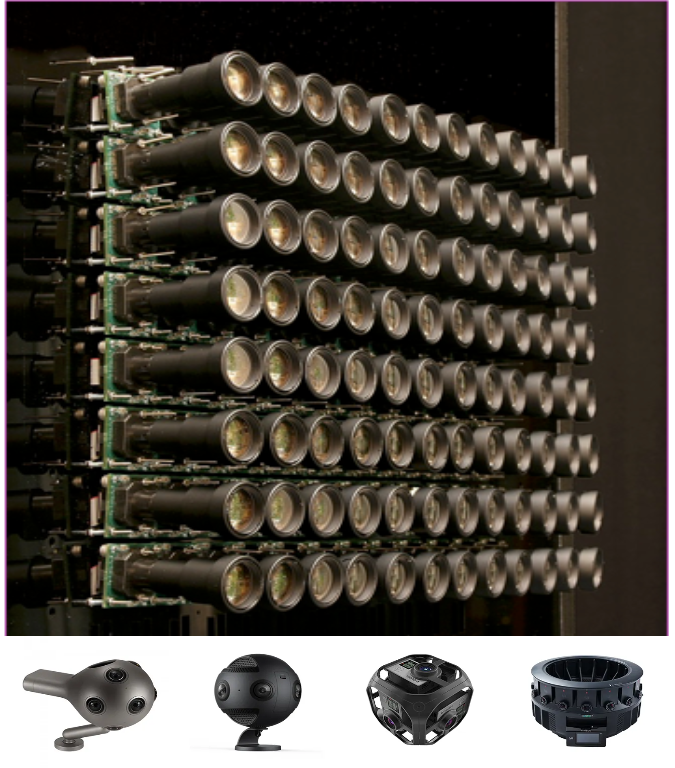
Engineers have built camera arrays that capture many incident light fields simultaneously. By measuring from multiple positions and directions, these systems can create immersive displays that reproduce the experience of moving and looking around within a scene. If the scene is static, a single moving camera can achieve the same result.
A large camera array built at the Stanford Graphics Lab illustrates this principle , Figure 2.5. The array shown at the top of the figure captures views from many positions, all pointing in the same direction. This setup allows a viewer to experience moving side-to-side or forward and backward. The arrays at the bottom, with cameras pointing outward from a central point, capture the light field from many directions. This allows a viewer to experience looking around from a fixed position. By combining these approaches, systems can capture enough data to simulate both movement and changes in gaze direction (Thatte et al. 2017). These camera arrays capture a coarse but powerful sample of the environmental light field, enabling the rendering of novel viewpoints through interpolation.
2.6 Optical light field
The optics of an imaging system—whether a pinhole, a simple lens, or a complex multi-element lens—transform the incident light field into a new light field inside the camera. This optical light field exists in the space between the exit pupil of the optics and the sensor. The journey of light begins in the environment, is narrowed to the incident light field at the entrance pupil, and is then transformed by the optics into the optical light field. The sensor, whether a digital chip or the retina, measures this optical light field5.
While the environmental and incident light fields are naturally described by a ray’s position and angle, the optical light field is often described differently. Because we are interested in the rays that travel from the optics to the sensor, it is convenient to parameterize them by their start and end points. We can define a ray by its position \((u,v)\) on the exit pupil plane and its destination \((r,c)\) on the sensor plane. This is often called the two-plane parameterization.
Using this convention, we can describe the optical light field as a function of these four spatial parameters, along with wavelength and polarization:
\[ L_O(u,v,r,c,\lambda,\rho) \tag{2.3}\]
This parameterization is particularly useful because it directly relates to what a light field sensor measures. Of course, it is possible to convert between this two-plane representation and the position-angle representation used for the other light fields.
The data recorded by the sensor is all we have to create an image or interpret the scene. The ability of any system to derive information from the light field is ultimately limited by what portion of the environmental light field passes through the optics to become the optical light field and is finally captured by the sensor.
2.7 Measuring the light field
How do we measure a light field? A pinhole camera offers a simple conceptual answer. An image from a pinhole camera is a measurement of the incident light field at the pinhole’s location. The intensity at each image point corresponds to the intensity of a small bundle of rays arriving from a single direction. To learn more about the environmental light field, we can follow Leonardo’s lead and move the pinhole to different locations, accumulating information with each measurement.
The camera arrays in Figure 2.5 are a practical implementation of this idea. They sample the environmental light field by measuring the incident light field at multiple camera positions. However, these cameras use lenses, not pinholes. A lens gathers light from across its entire aperture, and a conventional sensor integrates all of this light. For any single point on the sensor, the rays in the optical light field arrive from many positions within the lens’s exit pupil. A conventional sensor sums the energy from all these rays, losing the information about where each ray originated in the pupil. Consequently, a conventional camera measures an integrated version of the light field, not the full angular distribution of light at each point.
While a conventional camera array does not capture the complete light field, it captures enough information for its intended purpose: rendering a scene from various viewpoints by interpolating between the captured images. The light field concept is a powerful theoretical guide for the design and interpretation of such systems, even when the full light field is not measured.
In many scientific and clinical applications, a more precise measurement of the light field is essential. A key application is characterizing how an optical system transforms an incident light field into an optical light field (Equation 2.3). For example, astronomers measure the light from a distant star to understand how parallel rays are distorted by the atmosphere and their telescope optics. They use this information to build adaptive optics systems (Section 22.5) that correct for these distortions, ensuring that rays from a point source converge to a sharp point in the final image.
A second example is measuring the optics of the human eye. Imperfections in a person’s cornea and lens can be corrected with spectacles or laser surgery. To design these corrections, we must first measure how the eye’s optics transform incoming light rays. These measurements are central to the fields of ophthalmology and vision science, as we will explore further in Chapter 22.
A sensor design that directly captures the optical light field was invented by Adelson and Wang (1992). They placed a lenslet array in front of a standard camera sensor. Each lenslet covers a small group of pixels. As Figure 2.7 illustrates—using a pinhole array rather than lenslet for simplicity—rays arriving from different angles are captured by different pixels behind the pinhole. This sensor records both the position of a ray (which lenslet or pinhole) and its angle (which subpixel). Adelson and Wang (1992) describe how to use this information to estimate depth. The ideas was further developed by Ren Ng and his colleagues. Ng formed company, Lytro, that commercialized light field cameras (Ng et al. 2005). These cameras allow users to perform novel operations, such as refocusing an image after it has been captured (Section 20.3).
The principles of the light field camera continue to be used in modern sensors. While full depth estimation is not common in consumer devices, many cameras use a simplified version of this technology for autofocus (Section 18.2). We will return to light field cameras in Section 20.3 and discuss the parallel developments of Shack-Hartmann wavefront sensing in Section 22.5.1.
2.8 Interpreting the light field
Encoding the light field data is the first step in seeing. The instrumentation for encoding is a critical bottleneck because it limits what we can infer about the scene. For example, if an instrument does not record information about certain wavelengths, we can only guess at the missing information, for instance, by choosing the most likely value based on context.
Knowledge of the light field encoding is always connected to the next step in an image system: interpreting the measurement. The invention of algorithms that interpret the light field—to recognize objects or measure distances—is central to building computers that see. Interpreting the light field is also important for consumer photography, where we may wish to distinguish a surface marking from a shadow, or the color of an object from the color of the ambient lighting. In vision science, a primary goal is to discover how the brain interprets the signal encoded by the retina.
We will review many algorithms for interpreting images, but one overarching principle has endured for centuries. The principle is that image systems, whether artificial or biological, should use the encoded signal to build an internal model of the scene. The great 19th-century scientist Hermann von Helmholtz described it this way:
The general rule determining the ideas of vision that are formed whenever an impression is made on the eye, is that such objects are always imagined as being present in the field of vision as would have to be there in order to produce the same impression on the nervous mechanism. [Italics in the original; from Treatise on Physiological Optics, Vol. III, 1867]
Understanding the light field—how it interacts with objects, how it is measured by instruments, and how it is interpreted—is fundamental to achieving that goal. We are still working on the project assigned to us by Helmholtz.
There are instruments that use different wavebands of the electromagnetic spectrum. A brief introduction is here.. More examples of instruments will be presented in later chapters.↩︎
PROVE HOW ALL OBJECTS, PLACED IN ONE POSITION, ARE ALL EVERYWHERE AND ALL IN EACH PART
“I say that if the front of a building—or any open piazza or field—which is illuminated by the sun has a dwelling opposite to it, and if, in the front which does not face the sun, you make a small round hole, all the illuminated objects will project their images through that hole and be visible inside the dwelling on the opposite wall which may be made white; and there, in fact, they will be upside down, and if you make similar openings in several places in the same wall you will have the same result from each. Hence the images of the illuminated objects are all everywhere on this wall and all in each minutest part of it. The reason, as we clearly know, is that this hole must admit some light to the said dwelling, and the light admitted by it is derived from one or many luminous bodies. If these bodies are of various colours and shapes the rays forming the images are of various colours and shapes, and so will the representations be on the wall. (Leonardo’s 1509 Notebook, curated by John Paul Richter)”↩︎I enjoyed the first sentence in the 1939 translation of Gershun’s (1939) paper. The translators, Moon and Timoshenko, express frustration with the pace of advances in photometry. “Theoretical photometry constitutes a case of ‘arrested development’, and has remained basically unchanged since 1760 while the rest of physics has swept triumphantly ahead.” Gershun himself expresses the same sentiment: “The problems of theoretical photometry were pushed aside from the main path of the development of physics.”↩︎
Adelson and Bergen (1991) introduced the plenoptic function for a pinhole camera and a sensor, making it closely related to the incident light field. (Section 2.5). Using a pinhole camera model, the two parameters describing the aperture position are not needed. With these restrictions the plenoptic function becomes equivalent to the spectral irradiance at the image sensor (Wandell and Brainard 2021). The authors clearly had the idea of the environmental and incident light fields in mind.↩︎
Ren Ng used the phrase ‘in-camera light field’ in his Ph.D. thesis (Ng et al. 2005). I like that expression, too.↩︎